Alternating current (AC) circuit analysis is one of the most heavily tested topics across ECET, GATE (EC/EE), diploma and B.Tech semester exams — and it's also where most students lose easy marks, simply because the phase relationship between voltage and current is never revised side-by-side for every circuit type. In this article we compare all the fundamental AC circuits — Pure R, Pure L, Pure C, and their series and parallel combinations — in one place, with the waveform and phasor picture for each.
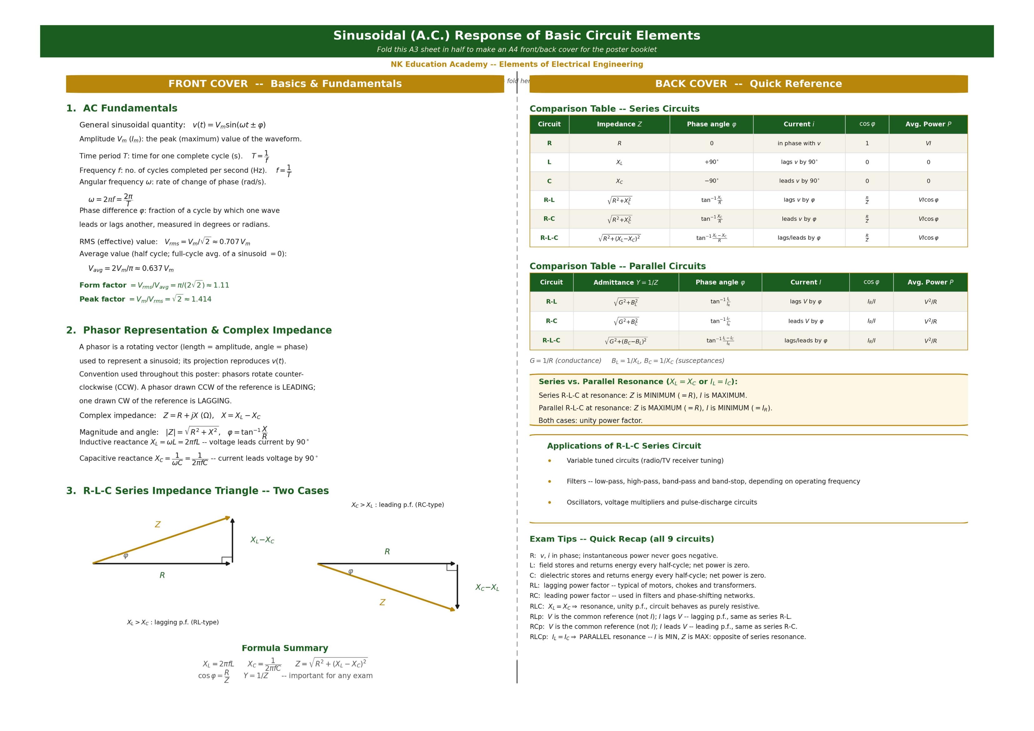
Poster Cover — AC Fundamentals & Quick Reference
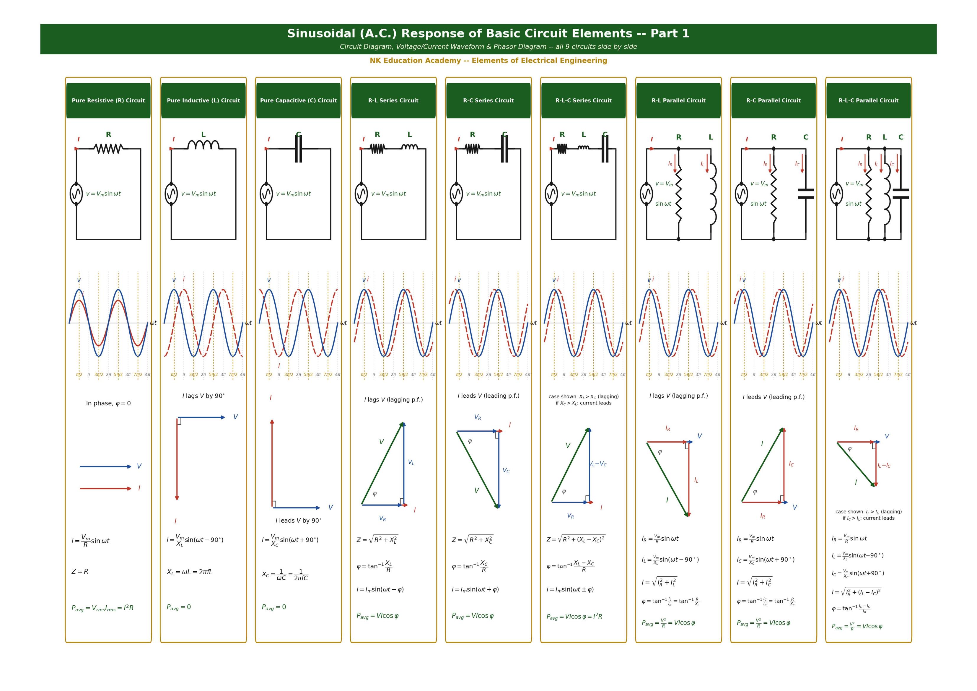
Part 1 — Circuit, Waveform & Phasor Diagrams for All 9 Circuits
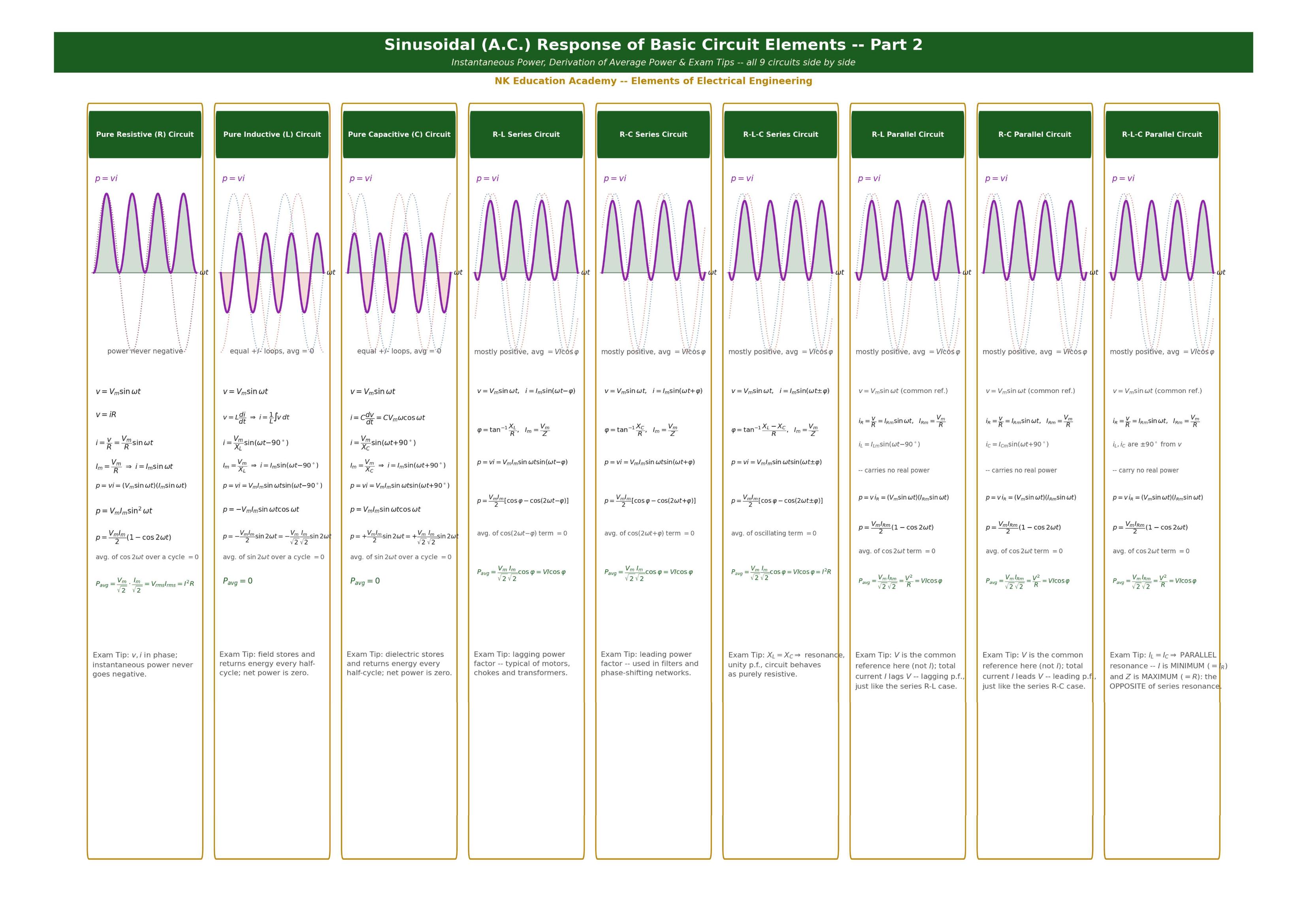
Part 2 — Instantaneous Power, Derivations & Exam Tips for All 9 Circuits
Comparison Table — Series Circuits
| Circuit | Impedance Z | Phase angle φ | Current i | cos φ | Avg. Power P |
|---|---|---|---|---|---|
| R | R | 0 | in phase with v | 1 | VI |
| L | XL | +90° | lags v by 90° | 0 | 0 |
| C | XC | −90° | leads v by 90° | 0 | 0 |
| R-L | √(R²+XL²) | tan⁻¹(XL/R) | lags v by φ | R/Z | VI cos φ |
| R-C | √(R²+XC²) | tan⁻¹(XC/R) | leads v by φ | R/Z | VI cos φ |
| R-L-C | √(R²+(XL−XC)²) | tan⁻¹((XL−XC)/R) | lags/leads by φ | R/Z | VI cos φ |
Comparison Table — Parallel Circuits
| Circuit | Admittance Y = 1/Z | Phase angle φ | Current I | cos φ | Avg. Power P |
|---|---|---|---|---|---|
| R-L | √(G²+BL²) | tan⁻¹(IL/IR) | lags V by φ | IR/I | V²/R |
| R-C | √(G²+BC²) | tan⁻¹(IC/IR) | leads V by φ | IR/I | V²/R |
| R-L-C | √(G²+(BC−BL)²) | tan⁻¹((IL−IC)/IR) | lags/leads by φ | IR/I | V²/R |
G = 1/R (conductance); BL = 1/XL, BC = 1/XC (susceptances)
Exam Tips — Quick Recap (All 9 Circuits)
- R: v, i in phase; instantaneous power never goes negative.
- L: field stores and returns energy every half-cycle; net power is zero.
- C: dielectric stores and returns energy every half-cycle; net power is zero.
- R-L: lagging power factor — typical of motors, chokes and transformers.
- R-C: leading power factor — used in filters and phase-shifting networks.
- R-L-C: XL = XC ⇒ resonance, unity p.f., circuit behaves as purely resistive.
- R-L Parallel: V is the common reference (not I); I lags V — lagging p.f., same as series R-L.
- R-C Parallel: V is the common reference (not I); I leads V — leading p.f., same as series R-C.
- R-L-C Parallel: IL = IC ⇒ PARALLEL resonance — I is MIN, Z is MAX: opposite of series resonance.
Conclusion
Need more worked examples and exam-focused practice on AC circuits? Our ECE/EEE and GATE coaching covers this topic in depth with numerical practice and past-paper questions. Enquire about batches →